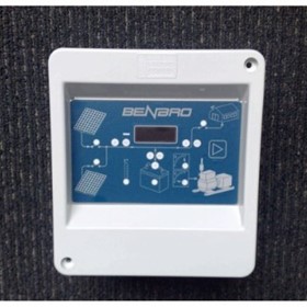
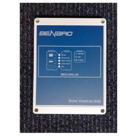
Benbro Monitor Module | Series 300
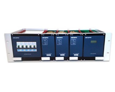
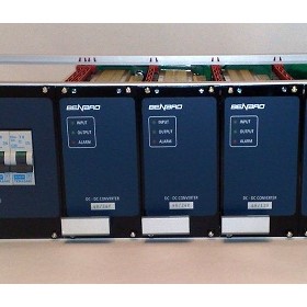
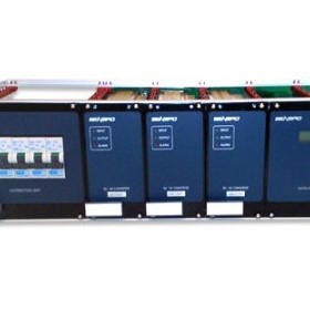
It has been designed for ease of installation and maximum flexibility of configuration. The Monitor Module plugs directly into the Subrack frame system backplane and takes up the spare 6HP space in the subrack plus 1 DC-DC converter slot.
The Monitor Module consists of a PCB that slides into the card guide slots and plugs into the backplane, an aluminium front panel and a 2 x 8 digit LCD (to display Voltage, Current and alarm status information). All external connections to the Monitor Module are made utilising the I/O connectors on the backplane PCB.
Links on the Monitor Module PCB are provided to facilitate alarm sounder disable and alarm relay configuration functions. The unit is shipped pre calibrated and requires no further calibration prior to use.
Features
Installation
To install the Monitor module
Remove the 6HP blanking panel on the right hand side of the Subrack frame (if fitted). Remove the right hand 13HP blanking panel (if fitted) or remove the DC – DC converter if fitted in the right hand converter slot.
Configure Alarm sounder
Configure link 4 (LK4) on the monitor unit PCB, the link should be in for the alarm sounder to operate or the link should be removed to disable the alarm sounder.
Configure Alarm relay output contacts.
Alarm 1 = DC-DC Fail. Alarm 2 = C/B Fail. Alarm 3 = Auxiliary.
Configure Alarm 1(DC-DC fail) contacts by shifting LK1 for open on Alarm (OA) or closed on alarm (CA)
Configure Alarm 2(C/B fail) contacts by shifting LK2 for Open on Alarm (OA) or closed on alarm (CA)
Configure Alarm 3(Auxiliary) contacts by shifting LK3 for Open on Alarm (OA) or closed on alarm (CA)
Note: Alarm relays are factory configured for Open on alarm (OA)
Fit the Monitor Module
Align the PCB of the accessory module with the card guides in the Subrack. Slide the accessory module into the Subrack until it engages into the backplane PCB. Engage the 4 Monitor module front panel screws into the Subrack rails and tighten.
To connect the Monitor Module inputs and outputs;
The Input Voltage to the Monitor Module is supplied from the combined output of the Benbro series 300 DC-DC converters that are fitted to the Subrack and is connected via the multi-way DIN 41612 immediately the Monitor Module is plugged in. The input Voltage range is 10VDC – 60VDC making it suitable for use with any Benbro series 300 converter. The equipment is protected by a self resetting input thermal fuse.
When the equipment is powered up it will display the software version during initialisation and will display the System Voltage on the top line of the LCD and the load current on the bottom line of the LCD and the Alarm status (prioritised) thereafter.
The DC Voltage (being measured) is also connected via the multi-way DIN 41612 connector immediately the Monitor Module is plugged in. The input Voltage range is 10VDC – 60VDC making it suitable for use with any Benbro series 300 converter. The DC Voltage is connected through 2 self resetting input thermal fuses (one on the positive and one on the negative).
The system Voltage will be displayed on the top line of the LCD unless overridden by an alarm function
The backplanes provide multiple options for current metering
Option 1 onboard current shunt.
The pre calibrated 100Amp 40mV on board current shunt is connected via the multi-way DIN 41612 connector immediately the Monitor Module is plugged in (through LK1 & LK2 on the backplane), LK1 & LK2 select the local (LOC) onboard shunt or an external (EXT) shunt supplied by others, they are factory set to Local (LOC).
Short AUX2 connector (J19) to select the 100Amp 40mV shunt calibration (Factory default)
Note To route the output current from an adjacent backplane PCB through the onboard current shunt (to include it in the total current measured) connect the output terminal of the adjacent Backplane PCB to the – Shunt terminal bus(-SH) (see Subrack frame manual)
The load current will be displayed on the bottom line of the LCD unless overridden by an alarm function
Option 2 external current shunt
An external current shunt can be selected by shifting the jumper link of LK1 & LK2 from Local (LOC) to external (EXT). The sense output of the external shunt should be connected to the green 2 pole shunt input connector marked +EXT- SHUNT. This input is polarity sensitive observe the correct polarity.
Short AUX2 (J19) to select the 100Amp 40mV shunt calibration (Factory default) or leave AUX2 (J19) open circuit to select 100Amp 50mV calibration.
The load current will be displayed on the bottom line of the LCD unless overridden by an alarm function
The DC-DC converter modules are each equipped with a converter fail alarm relay that is normally energised when the converter is operating correctly, the alarm output of the converter is factory configured for normally open operation and the contacts close on alarm (CA). The DC-DC Fail alarms are combined (paralleled) on the Subrack unit backplane PCB, they are connected via the multi-way DIN 41612 connector immediately the Monitor Module is plugged in.
Additional DC-DC fail alarms can be combined by connecting into the DC-DC FAIL input connector (J13) on the Backplane PCB or by connecting into the PS FAIL connector (J5) these inputs are in parallel and monitor remote voltage free contacts that close on alarm (CA)
When an alarm condition is detected the monitor will display DC-DC ALARM the alarm sounder will operate (unless disabled) and alarm relay 1 will operate.
Alarm relay 1 output contacts are extended to the Subrack backplane PCB and are marked Alarm 1(J16)
A load circuit breaker can be monitored by extending the contacts of the load circuit breaker into the CB FAIL input connector (J14) on the Backplane PCB. Polarity is unimportant as the input of the Monitor is dual polarity.
Multiple load circuit breakers can be monitored by combining the load side of the circuit breakers using a diode per circuit breaker to a common point in the normal way (Distribution modules are factory equipped for combined alarms that can be configured for common positive or common negative)
An alarm condition exists when a load circuit breaker that is connected to a load is off or tripped (if no load is connected no alarm condition will exist irrespective of the state of the circuit breaker)
When an alarm condition is detected the Monitor will display C/B ALARM the alarm sounder will operate (unless disabled) and alarm relay 2 will operate
Alarm relay 2 output contacts are extended to the Subrack backplane PCB and are marked Alarm 2(J17)
Remote equipment alarms can be monitored by the Monitor module.
The remote equipment alarm (closed on alarm (CA) Voltage free contacts) can be connected into the AUX input connector (J15) on the Backplane PCB
When an alarm condition is detected the Monitor will display AUX1 ALARM the alarm sounder will operate (unless disabled) and alarm relay 3 will operate
Alarm relay 3 output contacts are extended to the Subrack backplane PCB and are marked Alarm 3(J18)
To contact Benbro Electronics about Benbro Monitor Module | Series 300 use Get a quote.
Thanks for your help!
Sorry! Unable to submit your request at this time. Please try again later.
Report this product